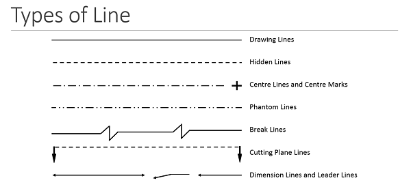
The most common type of line is the continuous line. Many people refer to this as a drawing line.

Engineering Design And Cad A B Line Types Flashcards Quizlet
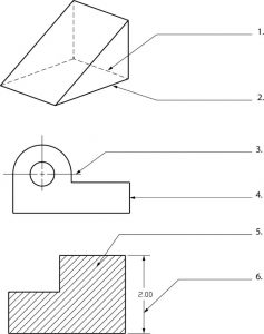
Detail Views A detail view is a separate large-scale drawing view of a small section of another view.
. The set of these points is called a line. Object lines stand out on the drawing and clearly define the outline and features of the object. It is an axonometric projection in which the three coordinate axes appear equally foreshortened and the angle between any two of them is 120 degrees.
Therefore any surface that is not in line with the three major axis needs its own projection plane to show the features correctly. Hidden Lines Thin type lines consist of thin short dashes closely and evenly spaced. An isometric view of a rectangular block is shown in Fig.
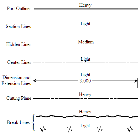
Three orthographic views in firstangle projection are given in Fig. Object lines Object lines Figure 3 are the most common lines used in drawings. Draw the line firmly with a free and easy wrist-and-arm motion.
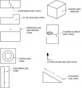
A hidden line also known as a hidden object line is a medium weight line made of short dashes about. The technical drawing is a form of design communication based on line symbols recognized and understood worldwide. K half section The view Obtained When the cutting plane goes half way across the Object to the centre line.
Axes and Other Lines in 3D Figure 24. A line representing changes of pressure or temperature under conditions of constant volume. Visible lines are the edges or outlines of an object.
It is an axonometric projection in which the three coordinate axes appear equally foreshortened and the angle between any two of. Only solid lines on the drawing represent visible edges. Note all the lines you find on an engineering drawing are equal.
Just as the points can be arranged in a number of fashions. The most fundamental parameter to define any engineering design is a point. It is assumed that an object is placed in front of a screen and light projected on the object assuming that the rays of light to be parallel to each other and perpendicular to the screen then a true shadow of.
These lines are drawn to represent hidden or invisible edges of the objects. The article talks about Line Types and Dimensions in Engineering drawing. An engineering drawing is a 2-dimensional representation of a 3-dimensional object.
In general application thick lines are 06 mm024. Thick and visible line. Thin hidden lines are used as intermittent line types.
These lines are used for the main lengths of the object view. Here oblique axis is called as receding axis. Use the solid lines to visualize the object in 3-dimensional space.
These thick solid lines show the visible edges corners and surfaces of a part. The object lies In between the observer and the plane of projection. The corners of the block are used to position a line DF in space.
Object lines stand out on the drawing and clearly define the outline and features of the object. 07 mm dashed lines that extend past the edge of the object6 mmand have line segments at each end drawn at90 degrees and. This line is located in front of cutting planes outlines of adjacent parts censorial Lines and to state center of gravity.
It represents an objects physical boundaries. Engineering Working Drawings Basics Page 8 of 22 parallel to the object surface. This line is used to represent the center line for circles and arcs.
Object lines are used in hand drawing and CAD to define the edges of the view being drawn. There are various options available making it possible to show hidden and visible edges of parts. Cubic Corners The linear systems in their simplest form use one equation for where m is the 2D length of line VA and F and G.
Line weight is the thickness of the line. Basic Types of Lines Used in Engineering Drawings By Kelly Curran Glenn Sokolowski. Definition of isometric line.
Line Drawing Perpendicularity Tools In practice by making assumptions about for Creative Design engineering objects and the ways people see and depict them it is often. The plan on which the projection of the object is taken is called the projection plan. Linetypes And Weight Standards In Technical Drawing.
Isometric projection is a method for visually representing three-dimensional objects in two dimensions in technical and engineering drawings. This line is used to represent the location of a cutting plane. Centre lines Lines of Symmetry Trajectories and Pitch Circles.
Technical drawings provide clear and accurate information how an object is to be manufactured. The right hand end viewside view Is drawn to the left and left hand end view Is drawn to. PACVarley RRMartin HSuzuki Using Depth Reasoning to Label Line Drawings of Engineering Objects -k -k A i j i j A G B G V F V B F E E -j -i -j -i k k C C Figure 23.
The object is assumed to be placed in first quadrant. Full section The view obtained even the cutting plane is right across the object. That is it is a type of line used.
A line such as a contour line drawn on a map and indicating a true constant value throughout its extent. An isometric view of a rectangular block is shown in Fig. In this highly interactive object learners associate basic line types and terms with engineering drawing geometry.
Many other line types exist and are used to communicate things like interior detail but object lines are the darkest lines on the pagescreen. A visible line or object line is a thick continuous line used to outline the visible edges or contours of. Drawing as a solid object an infinite number of possible solid objects could if viewed from the appropriate viewpoint result in the same line drawing.
Hold the pencil naturally. The imaginary lines drawn from the object to the plane are called projectors or projection lines. They are drawn as solid lines with a thickheavy weight.
Object line Figure 3 Object lines Hidden lines. This line is used to represent the center line for circles and arcs. Imagine sketching the front view of a house.
Layout of Drawing Sheet. Broken lines that appear in the drawing represent other aspects that are important for you to visualize the object. Thin lines are nearly 03 mm012 in most technical drawings.
This gives rise to number of important line types. A quiz completes the activity. In oblique projection the object is aligned such that one face front face is parallel to the projection plane.
112 and it will be apparent that the projected length of the line DF in each of the views will be equal in length to the diagonals across each of the rectangular faces. Construction lines and guide lines are very light easily erased lines used to block in the main layout. In such projection the projectors are not perpendicular to the plane of projection rather inclined to the plane of projection at 30 45 or 60.
2 The Language of Lines Object Line. It is used for symmetrical objects the same either side of the centre line. All other lines contrast with the visible lines by having either a thinner weight.
This line is used to show hidden edges of the main object. The front view or the elevation Is always above the top view or the plan. Isometric projection is a method for visually representing three-dimensional objects in two dimensions in technical and engineering drawings.
There are three major types of sections used in engineering drawing. Swing the pencil back and forth between the points barely touching the paper until the direction is clearly established. The plane of projection Is always behind the object.
Although THICK lines of Type-E are recommended for representing the hidden edges THIN lines of Type-F are preferred. Hence technical drawing is often referred to as. Spot the beginning and end points.
It shows and describes clearly and accurately the information required to build or manufacture a product.
Line Conventions Manufacturinget Org

Engineering Drawing Wikipedia
The Language Of Lines Basic Blueprint Reading
The Language Of Lines Basic Blueprint Reading

What Are Lines Types Of Lines In Engineering Drawing Youtube
What Is The Use Of The Continuous Line In Engineering Drawing Quora
How To Read Engineering Drawings A Simple Guide Make Uk

Engineering Drawing Notes B Drawings Engineering Types Of Drawing
0 comments
Post a Comment